Industries

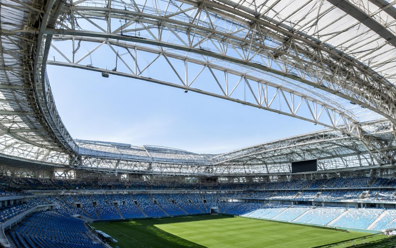
Infrastructure & Stadia

Long-span roofs, trusses and public-infrastructure steelwork.

Quick answer

Structural Engineering Services supports Infrastructure & Stadia projects worldwide with long-span roof structures, structural design services, tekla 3d modeling, steel connection design — delivered by senior engineers on licensed software to international codes.

1,200+
Projects delivered
40+
Countries served
60+
In-house engineers
2009
Engineering since

Governing codes

  • AISC 360 / AISC 303
  • EN 1993-1-1 / -1-8
  • AS 4100 / AS 1170
  • EN 1991-1-1 & crowd guidance
  • AWS D1.1 / EN ISO 3834

Sector challenges

What makes Infrastructure & Stadia engineering hard

Long-span and public structures are seen by everyone and inspected by everyone. The geometry is ambitious, the connections are on display, and the tolerances have to work on a site where nothing is square.

Challenge 01

Long spans and deflection control

Beyond about sixty metres the structure is governed by deflection, pre-camber and dynamic response, not by member strength.

How we answer it

Spans are checked for serviceability and footfall response, pre-camber is calculated and shown on the drawings, and erection-stage geometry is set so the finished shape is the designed one.
Challenge 02

Thermal movement and bearings

Large roofs move with temperature and will crack whatever they are restrained against.

How we answer it

Movement joints and sliding or pinned bearings are designed with calculated travel, and the restraint system is set out so the structure expands where it is intended to.

Challenge 03

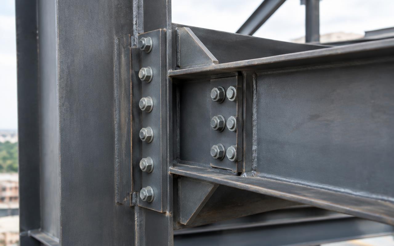
Exposed, complex connections

Architecturally exposed steelwork puts the connection on display and the tolerance under scrutiny.

How we answer it

AESS connections are designed with weld class, grinding and finish requirements noted on the drawing, and node geometry is resolved in the 3D model before steel is ordered.

Challenge 04

Erection engineering

A long-span truss is at its most vulnerable half-built, sitting on temporary towers in the wind.

How we answer it

Erection stages are analysed with temporary supports, stability checks and a jack-down sequence, so the method statement is backed by calculation rather than experience alone.

Relevant services

Our Infrastructure & Stadia services

Typical assets

Structures and equipment we engineer for infrastructure & stadia

From a single assembly to a complete package — the asset types our infrastructure & stadia teams work on week to week.

Stadium & arena roofs

Cantilever roofs, compression rings and cable-supported or trussed arena structures.

Long-span trusses & space frames

Trusses, space frames and lattice shells for halls, hangars and terminals.

Transport terminals

Terminal roofs, canopies, link bridges and concourse structures.

Footbridges & walkways

Pedestrian bridges and link walkways including vibration serviceability.

Canopies & entrance steel

Feature canopies, porte-cocheres and tensile structure support steel.

Grandstand steel

Raker beams, terracing supports and stand framing under crowd dynamic loads.

Codes & specifications

What governs infrastructure & stadia design

The base code is only half the story. On infrastructure & stadia work the client specification usually overrides it somewhere, so we agree a single reconciled design basis before any calculation starts.

Browse all codes
  • AISC 360 / AISC 303

    Member and connection design plus the code of standard practice that defines AESS categories.

  • EN 1993-1-1 / -1-8

    Eurocode member and joint design, paired with EN 1090 execution class.

  • AS 4100 / AS 1170

    Australian projects: steel design with wind and seismic actions.

  • EN 1991-1-1 & crowd guidance

    Crowd loading and synchronised movement criteria for grandstands and footbridges.

  • AWS D1.1 / EN ISO 3834

    Welding qualification and quality levels for highly stressed, visible welds.

  • ASCE 7 / EN 1991-1-4

    Wind actions on large roofs, including internal pressure on open-sided structures.

Free quote

Not sure what you need?

Send the drawings or datasheets you already have. We will tell you what is missing and quote the scope in 24 hours.

Request a Quote

Project lifecycle

Where we plug into a infrastructure & stadia project

Most clients bring us in at detailed design. We can start earlier, or pick a package up mid-stream — here is what you get from us at each stage.

01

Concept & feasibility

Options, preliminary sizing and budget tonnage, before the scheme is frozen.

Structural concept with the architect, span strategy and indicative member depths.

You receive

  • Design basis memorandum
  • Preliminary weight and tonnage estimate
  • Framing concept and first-pass member sizing
  • Scheme comparison under preliminary load cases
  • Massing and framing sketches coordinated with the architect
02

FEED / basic design

Design basis, load schedules and layouts good enough to price and procure from.

Scheme analysis, movement strategy and connection philosophy for tender.

You receive

  • Load schedule and design criteria
  • GA drawings good enough to price
  • Connection philosophy and tonnage take-off
  • Governing load combinations fixed per code
  • Movement, bearing and expansion joint strategy
03

Detailed design

Full analysis, code checks, 3D modelling and issued-for-construction documentation.

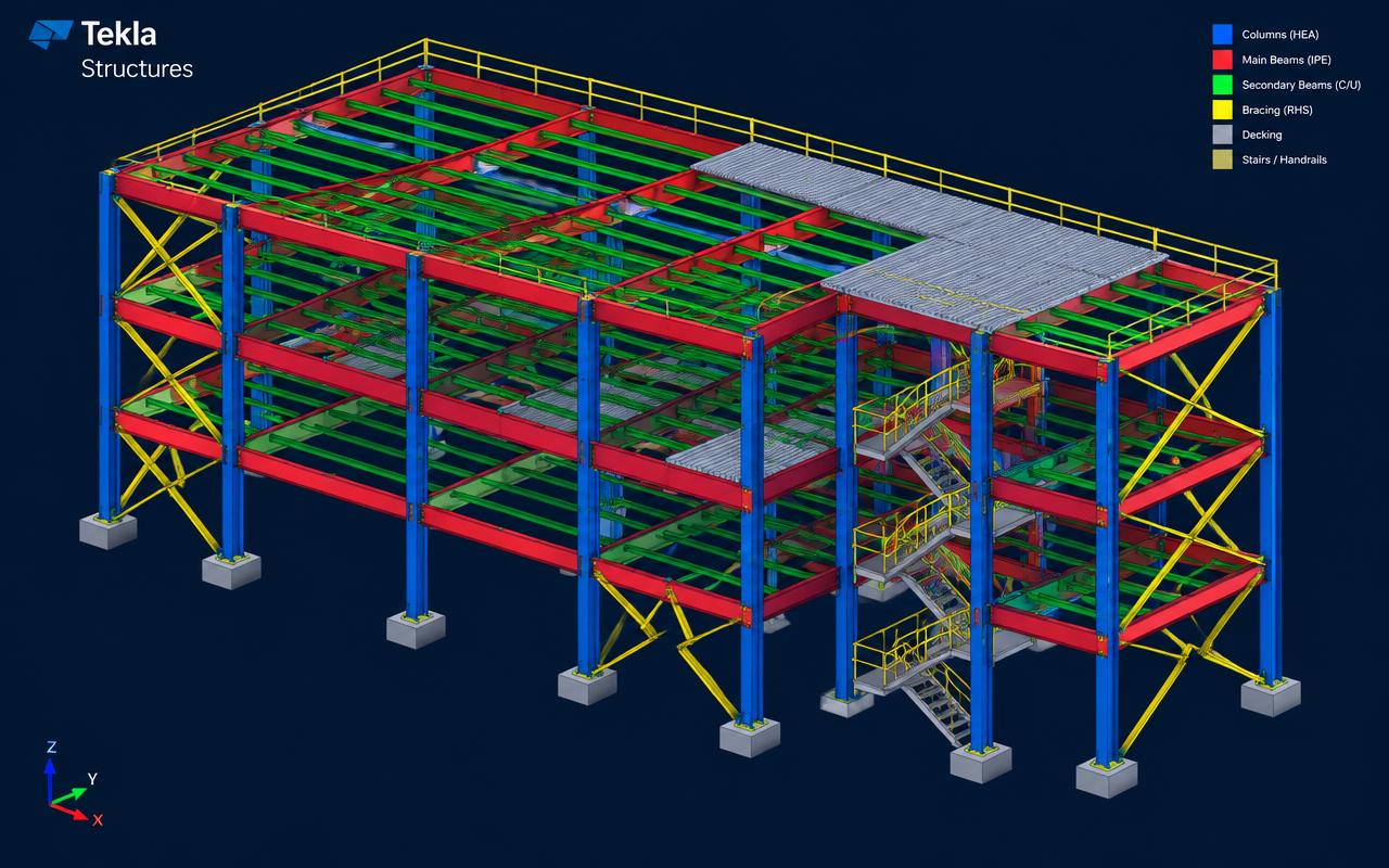
Staged erection analysis, node and connection design, Tekla model at LOD 400.

You receive

  • Checked design calculation report
  • Issued-for-construction drawing set
  • LOD 400 Tekla model with shop and erection drawings
  • Member, connection and foundation design sheets
  • Pre-camber and node coordinate schedule
04

Fabrication & site support

Shop queries, RFIs and as-built updates while steel is being cut and erected.

Temporary works checks, survey and fit-up support, geometry reconciliation on site.

You receive

  • RFI and technical query log
  • As-built red-line mark-ups
  • NC/DSTV files and shop fit-up support
  • Field-change re-checks and repair calculations
  • Temporary works and jack-down sequence checks

Deliverables & handover

What you actually receive

Public-realm projects are handed over with the geometry control data — setting-out points, pre-camber and node coordinates — because the survey team on site needs numbers, not drawings.

DeliverableFormatIssued at
Design basis and calculation reportPDF, signed and checkedDetailed design
General arrangement drawingsDWG + PDFFEED to detailed design
Drawing register and transmittalXLSX + PDFEvery issue
Tekla 3D modelNative .db1 + IFC 2x3/4Detailed design
Single-part, assembly and erection drawingsPDF + DWG, one sheet per markDetailed design
CNC files, bolt list and BOQNC1/DSTV, DXF, XLSXPre-fabrication
Analysis model and load combinationsSTAAD .std + PDF summaryDetailed design
Connection and base-plate design sheetsPDF calculation packDetailed design
Pre-camber and erection-stage geometry scheduleXLSX + marked drawingsDetailed design
Erection stage and temporary works analysisPDF calculation + sequence drawingsPre-erection

Two-stage check

Originator, then senior checker signs off every sheet before it leaves our office.

Native files included

You own the model, so another team can pick the work up at any point.

Revision control

A revision table on every sheet; superseded issues are archived, never deleted.

Your transmittal route

Issued through your document-control portal with your numbering, or over secure FTP.

Directory

Infrastructure & Stadia engineering by market

Jump straight to the market you build in. Every page sets out the governing codes, units and delivery window we work to there.

8 markets

Start your project

Send your drawings. Get a quote in 24 hours.

Free, no-obligation proposal from a senior engineer.

Request a Quote
irPowered by IRPR